The
TD-881 Series offers the digital-set accuracy of DIP-switch setting as well as
the flexible programmability of a multi-function & multi-time range relay.
These products provide an easy & accurate method to select any of 16 time
delay functions and any time delay between 100ms and 1,023 hours (31 hours
maximum for Dual Mode functions). Programming is accomplished through the use
of two 10-position DIPswitches. This product can literally replace hundreds of
different catalog numbers, thereby reducing inventory requirements.
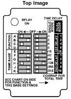
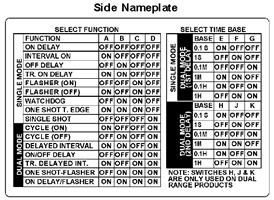
Programming is accomplished through the use of two 10-position DIP-switches
(see drawings at right). Switches A-D of the left-mounted DIP-switch are used
to select a function. Switches E-K of the same DIP-switch are used to select
the time base. A convenient chart is on the side of the relay to clearly
illustrate how to set both the function & time base. |
 |
|
|
| The
right-mounted 10-position DIP-switch is used to select the time delay within
the time base selected with switches E-K from the first DIP-switch. Each
position on the second DIP-switch is marked with a binary time increment. The
required delay is selected by moving the switch of each increment to the ON
position & adding their corresponding values. Note that dual mode products
can either have the same or different ON & OFF times. |
Features:
- Sixteen user-selectable modes in one unit
- DIP-Switches for accurate digital set of time delay &
selection of function
- 100ms - 1,023 hours programmable time delay (Single Mode
functions only)
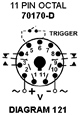
- Uses industry-standard 11 pin octal socket
|
|
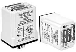
| Part Number |
Function |
Input Voltage |
Wiring Socket |
 TD-88122 TD-88122 |
Multi-Function - See table below
for list of timing functions. |
120V AC/DC |
 |
| TD-88126 |
12V AC/DC |
| TD-88128 |
24V AC/DC |
| TD-88121 |
240V AC |
| TD-88162 |
Multi-Function - See table below
for list of timing functions. |
120V AC/DC |
 |
| TD-88166 |
12V AC/DC |
| TD-88168 |
24V AC/DC |
| TD-88161 |
240V AC |
| Timing
Functions |
| Code / Function |
Operation |
Timing Chart |
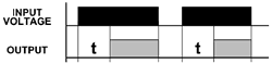
(A) ON DELAY
Delay on Operate
Delay on Make |
Upon application of input voltage, the time delay (t) begins.
At the end of the time delay (t), the output is energized. Input voltage must
be removed to reset the time delay relay & de-energize the output.. |
 |
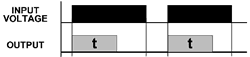
(B) INTERVAL ON
Interval |
Upon application of input voltage, the output is energized
and the time delay (t) begins. At the end of the time delay (t), the output is
de-energized. Input voltage must be removed to reset the time delay relay. |
 |
(C) OFF DELAY
Delay on Release
Delay on Break
Delay on De- Energization |
Upon application of input voltage, the time delay relay is
ready to accept a trigger. When the trigger is applied, the output is
energized. Upon removal of the trigger, the time delay (t) begins. At the end
of the time delay (t), the output is de-energized. Any application of the
trigger during the time delay will reset the time delay (t) and the output
remains energized. |
 |
(D) SINGLE SHOT
One Shot Momentary Interval |
Upon application of input voltage, the time delay relay is
ready to accept a trigger. When the trigger is applied, the output is energized
and the time delay (t) begins. During the time delay (t), the trigger is
ignored. At the end of the time delay (t), the output is de-energized and the
time delay relay is ready to accept another trigger. |
 |
(E) FLASHER
(Off First) |
Upon application of input voltage, the time delay (t) begins.
At the end of the time delay (t), the output is energized and remains in that
condition for the time delay (t). At the end of the time delay (t), the output
is de-energized and the sequence repeats until input voltage is removed. |
 |
(F) FLASHER
(ON First) |
Upon application of input voltage, the output is energized
and the time delay (t) begins. At the end of the time delay (t), the output is
de-energized and remains in that condition for the time delay (t). At the end
of the time delay (t), the output is energized and the sequence repeats until
input voltage is removed. |
 |
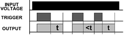
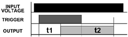
| (G) ON/OFF DELAY |
Upon application of input voltage, the time delay relay is
ready to accept a trigger. When the trigger is applied, the time delay (t1)
begins. At the end of the time delay (t1), the output is energized. When the
trigger is removed, the output contacts remain energized for the time delay
(t2). At the end of the time delay (t2), the output is de-energized & the
time delay relay is ready to accept another trigger. If the trigger is removed
during time delay period (t1), the output will remain de-energized and time
delay (t1) will reset. If the trigger is removed during time delay period (t2),
the output will remain energized and the time delay (t2) will reset. |
 |
| (H)SINGLE SHOT FALLING EDGE |
Upon application of input voltage, the time delay relay is
ready to accept a trigger. When the trigger is applied, the output remains
de-energized. Upon removal of the trigger, the output is energized and the time
delay (t) begins. At the end of the time delay (t), the output is de-energized
unless the trigger is removed and re-applied prior to time out (before time
delay (t) elapses). Continuous cycling of the trigger at a rate faster than the
time delay (t) will cause the output to remain energized indefinitely. |
 |
(J) WATCHDOG
Retriggerable Single Shot |
Upon application of input voltage, the time delay relay is
ready to accept a trigger. When the trigger is applied, the output is energized
and the time delay (t) begins. At the end of the time delay (t), the output is
de-energized unless the trigger is removed and re-applied prior to time out
(before time delay (t) elapses). Continuous cycling of the trigger at a rate
faster than the time delay (t) will cause the output to remain energized
indefinitely. |
 |
| (K) TRIGGERED ON DELAY |
Upon application of input voltage, the time delay relay is
ready to accept a trigger. When the trigger is applied, the time delay (t)
begins. At the end of the time delay (t), the output is energized and remains
in that condition as long as either the trigger is applied or the input voltage
remains. If the trigger is removed during the time delay (t), the output
remains de-energized & the time delay (t) is reset. |
 |
(L) REPEAT CYCLE
(OFF 1st) |
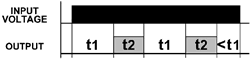
Upon application of input voltage, the time delay (t1)
begins. At the end of the time delay (t1), the output is energized and remains
in that condition for the time delay (t2). At the end of this time delay, the
output is de-energized and the sequence repeats until input voltage is
removed. |
 |
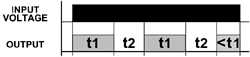
(M) REPEAT CYCLE
(ON 1st) |
Upon application of input voltage, the output is energized
and the time delay (t1) begins. At the end of the time delay (t1), the output
is de-energized and remains in that condition for the time delay (t2). At the
end of this time delay, the output is energized and the sequence repeats until
input voltage is removed. |
 |
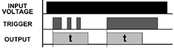
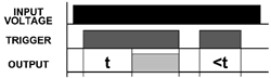
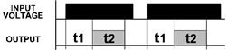
(N) DELAYED INTERVAL
Single Cycle |
Upon application of input voltage, the time delay (t1)
begins. At the end of the time delay (t1), the output is energized and remains
in that condition for the time delay (t2). At the end of this time delay (t2),
the output is de-energized. Input voltage must be removed to reset the time
delay relay. |
 |
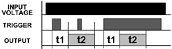
| (P) TRIGGERED DELAYED INTERVAL |
Upon application of input voltage, the time delay relay is
ready to accept a trigger. When the trigger is applied, the time delay (t1)
begins. At the end of the time delay (t1), the output is energized and remains
in that condition for the time delay (t2). At the end of the time delay (t2),
the output is de-energized & the relay is ready to accept another trigger.
During both time delay (t1) & time delay (t2), the trigger is ignored. |
 |
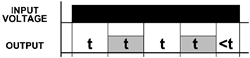
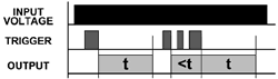
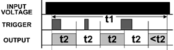
| (T) SINGLE SHOTFLASHER |
Upon application of input voltage, the time delay relay is
ready to accept a trigger. When the trigger is applied, the time delay (t1)
begins and the output is energized for the time delay (t2). At the end of this
time delay (t2), the output is de-energized and remains in that condition for
the time delay (t2). At the end of the time delay (t2), the output is energized
and the sequence repeats until time delay (t1) is completed. During the time
delay (t1), the trigger is ignored. |
 |
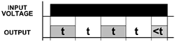
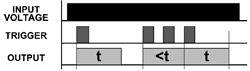
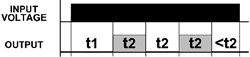
| (X) ON DELAY-FLASHER |
Upon application of input voltage, the time delay begins
(t1). At the end of the time delay (t1), the output is energized and remains in
that condition for the time delay (t2). At the end of this time delay (t2), the
output is de-energized and remains in that condition for the time delay (t2).
At the end of the time delay (t2), the output is energized and the sequence
repeats until input voltage is removed. |
 |
| Voltage Tolerance: |
AC Operation: +10/-15% of nominal at 50/60 Hz.
DC
Operation: +10/-15% of nominal. |
| Load (Burden): |
2 VA |
| Setting Accuracy: |
±1% of set time or ±50ms, whichever is
greater. |
| Repeat Accuracy (constant voltage and
temperature): |
±0.1% of set time or ±0.02 seconds, whichever
is greater. |
| Reset Time: |
All Functions Triggered by a Control Switch: 0.04 Seconds All
Other Functions: 0.1 Seconds |
| Start-up Time: |
(Time from when power is applied until unit is timing)
120 & 240V units 0.05 Seconds
12, 24 & 48V units 0.08 Seconds |
| Maintain Function Time: |
(Time unit continues to operate after power is removed)
0.01 Seconds for all units |
| Insulation Voltage: |
2,000 volts |
| Temperature: |
-28° to 65°C (-18° to 149°F) |
| Output Contacts: |
DPDT 10A @ 240V AC/30V DC, 1/2HP @ 120/240V AC (N.O.), 1/3HP
@ 120V AC (N.C.) B300 & R300; AC15 & DC13 |
| Life: |
Mechanical: 10,000,000 operations
Full Load: 100,000
operations |
| Compatibility: |
Using a solid state switch to initiate the time sequence is
acceptable. See www.macromatic.com/leakage for information regarding leakage
current limits and other solid state design considerations. |
| Control Switch Triggered Units: |
Minimum required trigger switch closure time is 0.02
seconds. |