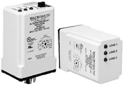
Macromatic ATP Series Triplexors are used in three load applications requiring both the optimization of load usage by equalizing the run time of multiple loads and additional capacity in case of excess load requirements.
As standard, these products operate as a normal Triplexor with three inputs. See "Typical Installations" below for more information. An optional version with an 8-position rotary switch is offered. This allows the unit to operate as either a:
- standard Triplexor
- Triplexor locking Load 1, 2 or 3 as the first to be
energized (Lead Load)
- standard Duplexor until system expansion requires
control for a third Load
- Duplexor locking Load 1 or 2 as the first to be
energized (Lead Load)
| |  |
| |
| All versions offer an indication of a switch failure (out-of-sequence)--LED..s will flash if any switch closes out of sequence. Also, if power is lost & returns with more than just the LEAD Switch closed, there is a fixed 10 second delay between energization of the first output & subsequent outputs to prevent all Loads from coming on at the same time. |
| | |
Features: - For Triplex Loads
- Works with 3 Switch inputs-- LEAD, LAG & LAG2
- Optional top-mounted switch allows use as standard
Triplexor or as Duplexor until system expansion requires additional third
Load
- Control voltages of 120V AC or 24V AC/DC
- Plug-in enclosure utilizes industry-standard 8 Pin octal
or 12 Pin square sockets
- Input Switch Failure Indication
| |
| Part Number | Function | Control Voltage | Wiring Socket |
 ATP120A1 ATP120A1 | Triplexor Only without Switch |
120V AC |  |
|
ATP024A1 | 24V AC/DC |
|
ATP120A1R |
Triplexor / Duplexor with Switch | 120V AC |
|
ATP024A1R | 24V AC/DC |
|
ATP120A7R | Triplexor / Duplexor with Switch | 120V AC |
 |
|
ATP024A7R | 24V AC/DC |
| Voltage Tolerances: | +10%/-15% at 50/60Hz. (AC); +10%/-15% of control voltage (DC) |
| Load (Burden): | Less than 2VA for all voltages |
| Output Contacts: | (3) SPNO 3A @ 24/120V AC General Purpose; C300 Pilot Duty; 1/6HP @ 24/120VAC |
| Life: | Mechanical: 10,000,000 operations, Full Load: 100,000 operations |
| Temperature: | -28° to 65°C (-18° to 149°F) |
| Transient Protection: | 10,000 volts for 20 microseconds |
| Time Delay: |
If power is lost & returns with more than just the LEAD Switch closed, there is a fixed 10 second delay between energization of the second output (Triplex & Duplex mode) & third output (Triplex mode only) to prevent all Loads from coming on at the same time. |
| LED Indication: | One of the Red LED..s will be steady ON to indicate which Load will be energized first; all will flash (3 in Triplex mode or 2 only in Duplex mode) to indicate a switch out-of-sequence error. |
| Optional Selector Switch Settings: | Allows unit to operate as standard Triplexor or Duplexor, or lock selected Loads to operate first (Lead Load) each time:
| Triplex |
Duplex |
| Triplex--Lead 1 |
Duplex--Lead 1 |
| Triplex--Lead 2 |
Duplex--Lead 2 |
| Triplex--Lead 3 |
|
|
| Typical Installations - 3 Switch 3 Pump |
| All three switches are open and all loads are off. When the LEAD Switch closes, it energizes Load 1. As long as the LEAD Switch remains closed, Load 1 remains energized. If the LAG Switch closes, Load 2 is energized. If the LAG2 Switch closes, it energizes Load 3. Each load is turned off in sequence as the switches are opened. The entire cycle is then repeated, but with Load 2 energized first followed by Load 3 and then Load 1. NOTE: power for outputs is supplied from L connection, not through input switches (see drawing below). | | | |  | |