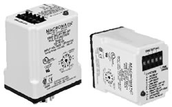
| The TD-781 Series
offers an easy and accurate way to select a function & any time delay
between 50ms & 999 hours. Programming is accomplished by using a pushbutton
thumbwheel to select one of seven built-in time ranges and three pushbutton
thumbwheels to digitally set the time delay required. This method provides a
greater setting accuracy than is found on other units with an analog
potentiometer. These units have a fifth pushbutton thumbwheel to select one of
ten built-in functions. An LED indicates timing mode and time out
condition. |
 |
Features:
- Ten user-selectable modes in one unit
- Pushbutton Thumbwheels for digital set of time delay
& function
- 50ms - 999 hour programmable time range
- Uses industry-standard 11 pin octal socket
- 10A DPDT output contacts
- LED indicates timing mode and time out conditions
|
|
| Part Number |
Function |
Input Voltage |
Wiring Socket |
 TD-78122 TD-78122 |
Multi-Function - See table below
for list of timing functions. |
120V AC/DC |
 |
| TD-78126 |
12V AC/DC |
| TD-78128 |
24V AC/DC |
| TD-78121 |
240V AC |
| Timing
Functions |
| Code / Function |
Operation |
Timing Chart |
(A) ON DELAY
Delay on Operate
Delay on Make |
Upon application of input voltage, the time delay (t) begins.
At the end of the time delay (t), the output is energized. Input voltage must
be removed to reset the time delay relay & de-energize the output.. |
 |
(B) INTERVAL ON
Interval |
Upon application of input voltage, the output is energized
and the time delay (t) begins. At the end of the time delay (t), the output is
de-energized. Input voltage must be removed to reset the time delay relay. |
 |
(C) OFF DELAY
Delay on Release
Delay on Break
Delay on De- Energization |
Upon application of input voltage, the time delay relay is
ready to accept a trigger. When the trigger is applied, the output is
energized. Upon removal of the trigger, the time delay (t) begins. At the end
of the time delay (t), the output is de-energized. Any application of the
trigger during the time delay will reset the time delay (t) and the output
remains energized. |
 |
(D) SINGLE SHOT
One Shot Momentary Interval |
Upon application of input voltage, the time delay relay is
ready to accept a trigger. When the trigger is applied, the output is energized
and the time delay (t) begins. During the time delay (t), the trigger is
ignored. At the end of the time delay (t), the output is de-energized and the
time delay relay is ready to accept another trigger. |
 |
(E) FLASHER
(Off First) |
Upon application of input voltage, the time delay (t) begins.
At the end of the time delay (t), the output is energized and remains in that
condition for the time delay (t). At the end of the time delay (t), the output
is de-energized and the sequence repeats until input voltage is removed. |
 |
(F) FLASHER
(ON First) |
Upon application of input voltage, the output is energized
and the time delay (t) begins. At the end of the time delay (t), the output is
de-energized and remains in that condition for the time delay (t). At the end
of the time delay (t), the output is energized and the sequence repeats until
input voltage is removed. |
 |
| (G) ON/OFF DELAY |
Upon application of input voltage, the time delay relay is
ready to accept a trigger. When the trigger is applied, the time delay (t1)
begins. At the end of the time delay (t1), the output is energized. When the
trigger is removed, the output contacts remain energized for the time delay
(t2). At the end of the time delay (t2), the output is de-energized & the
time delay relay is ready to accept another trigger. If the trigger is removed
during time delay period (t1), the output will remain de-energized and time
delay (t1) will reset. If the trigger is removed during time delay period (t2),
the output will remain energized and the time delay (t2) will reset. |
 |
| (H) SINGLE SHOT FALLING EDGE |
Upon application of input voltage, the time delay relay is
ready to accept a trigger. When the trigger is applied, the output remains
de-energized. Upon removal of the trigger, the output is energized and the time
delay (t) begins. At the end of the time delay (t), the output is de-energized
unless the trigger is removed and re-applied prior to time out (before time
delay (t) elapses). Continuous cycling of the trigger at a rate faster than the
time delay (t) will cause the output to remain energized indefinitely. |
 |
(J) WATCHDOG
Retriggerable Single Shot |
Upon application of input voltage, the time delay relay is
ready to accept a trigger. When the trigger is applied, the output is energized
and the time delay (t) begins. At the end of the time delay (t), the output is
de-energized unless the trigger is removed and re-applied prior to time out
(before time delay (t) elapses). Continuous cycling of the trigger at a rate
faster than the time delay (t) will cause the output to remain energized
indefinitely. |
 |
| (K) TRIGGERED ON DELAY |
Upon application of input voltage, the time delay relay is
ready to accept a trigger. When the trigger is applied, the time delay (t)
begins. At the end of the time delay (t), the output is energized and remains
in that condition as long as either the trigger is applied or the input voltage
remains. If the trigger is removed during the time delay (t), the output
remains de-energized & the time delay (t) is reset. |
 |
| Voltage Tolerance: |
AC Operation: +10/-15% of nominal at 50/60 Hz.
DC
Operation: +10/-15% of nominal. |
| Load (Burden): |
3 VA |
| Setting Accuracy: |
±1% of set time or ±50ms, whichever is
greater. |
| Repeat Accuracy (constant voltage and
temperature): |
±0.1% of set time or ±0.02 seconds, whichever
is greater. |
| Reset Time: |
On Delay/Interval/Flasher: 0.1 Seconds
Functions with
Control Switches: 0.04 Seconds |
| Start-up Time: |
(Time from when power is applied until unit is timing)
120 & 240V units 0.05 Seconds
12, 24 & 48V units 0.08 Seconds |
| Maintain Function Time: |
(Time unit continues to operate after power is removed)
0.01 Seconds for all units |
| Insulation Voltage: |
2,000 volts |
| Temperature: |
12-120V Input Voltage: -28° to 65°C (-18° to
149°F)
240V Input Voltage: -28° to 50°C (-18° to
122°F) |
| Insulation Voltage: |
2,000 volts |
| Output Contacts: |
DPDT 10A @ 240V AC/30V DC, 1/2HP @ 120/240V AC (N.O.), 1/3HP
@ 120/240V AC (N.C.) B300 & R300; AC15 & DC13 |
| Life: |
Mechanical: 10,000,000 operations
Full Load: 100,000
operations |
| Compatibility: |
Using a solid state switch to initiate the time sequence is
acceptable. See www.macromatic.com/leakage for information regarding leakage
current limits and other solid state design considerations. |
| Initiating Units with Control Switch
Triggers: |
Timing sequence must be initiated only after input voltage is
applied to unit. Minimum required trigger switch closure time is 0.1
seconds. |
| LED: |
Red LED. Refer to instruction sheet provided with product to
determine code for relay & timing status. |