Macromatic
Industrial Control & Monitoring Products |
|
| Phase Monitoring Relays | | PCP Series - Phase Reversal Monitor Relays | | PLP
Series - Phase Loss & Reversal Monitor Relays | | PAP
Series - Phase Loss, Reversal, & Undervoltage Monitor Relays | | PMP
Series - Phase Loss, Reversal, Unbalance, & Over/Under Voltage Monitor
Relays | | PMP-FA
Series - Phase Loss, Reversal, Unbalance, & Over/Under Voltage Monitor
Relays | | PMD
Series - Phase Loss, Reversal, Unbalance, & Over/Under Voltage Monitor
Relays | | Current Sensing Relays (AC) | | CM Series
- Standard | | CO Series
- Overcurrent | | CU Series
- Undercurrent | | Voltage Monitor Relays | | VM Series
- Over/Under Voltage Fixed Time Delay on Drop-Out 12-120V | | VA Series
- Over/Under Voltage Adj. Time Delay on Drop-Out 12-120V | | VAKPU
Series - Over/Under Voltage Adj. Time Delay on Pick-Up & Drop-Out
208-240V | | VW Series
- Voltage Band (Window) 12-120V | | VWKPU
Series Voltage Band (Window) 208-240V | | Alternating Relays | | ARP
Series - SPDT & DPDT Duplexor | | ARP
Series - DPDT Cross-Wired Duplexor | | ATP
Series - Triplexor | | Pump Seal Failure Relays | | SFP
Series - Single & Dual Channel | | Intrinsically-Safe Relays | | ISP
Series - Single Channel | | Time Delay Relays | | TR-6
Series - Time Ranger™ Programmable Multi-Range Plug-In with On Delay,
Interval ON, Flasher or True OFF Delay Functions | | TR-6 Series - Time Ranger™ Programmable Multi-Range
Plug-In with OFF Delay, Single Shot or Watchdog Functions | | TR-6 Series - Time Ranger™ Programmable Multi-Range
Plug-In with Repeat Cycle or Delayed Interval Functions | | TD-8 Series - DIP-Switch Digital-Set Multi-Function
Programmable Time Delay Relays | | TD-7 Series - Time Ranger™ Digital-Set Programmable
Multi-Range Multi-Function Time Delay Relays | | TD-7 Series - Time Ranger™ Digital-Set Programmable
Multi-Range Single-Function Time Delay Relays | | TAD
Series - Digital-Set Multi-Function Multi-Range 1/16 DIN Mounting | | TAA
Series - Analog-Set Multi-Function Multi-Range 1/16 DIN Mounting | | Sockets & Accessories | | Sockets and Accessories |
| | Macromatic ARP Series - DPDT Cross-Wired Duplexor - Alternating Relays (Plug-In) | | | | Alternating Relays with DPDT cross-wired outputs are used in applications requiring both (a) the optimization of load usage by equalizing the run time of two loads and (b) additional capacity in case of excess load requirements. This alternating action is initiated by a control switch, such as a float switch, manual switch, timing relay, pressure switch, or other isolated contact. Each time the initiating switch is opened, the output relay contacts will change state, thus alternating the two loads. Two LED indicators show the load to energize first.
Alternating Relays with DPDT cross-wired output configurations can be used with two or three control switches. See "Typical Installations" below for more information. | | 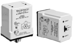
| | | | An optional three position selector switch is offered. This allows a DPDT cross-wired unit to alternate the two loads as normal, or lock the relay to always operate the same load first each time. In this manner, a load that has fewer hours of operation than the other load could be used more often in an effort to eventually balance the run time of both loads. | | | | Features: - For duplex loads
- 10A DPDT Cross-Wired Output Configuration when additional
capacity is required
- Can be used with two or three Control Switches
- Control voltages of 12, 24, 120 & 240V AC
- Compact plug-in design utilizing industry-standard 8 pin
octal socket
- Optional low profile selector switch to lock either load
ON first
- 2 LED..s indicate load to energize first
| | | Part Number | Output Contacts | Control Voltage | Wiring Socket |
 ARP012A3 ARP012A3 | DPDT Cross-Wired without Selector Switch | 12V AC |  | |
ARP024A3 | 24V AC | |
ARP120A3 | 120V AC | |
ARP240A3 | 240V AC | |
ARP012A3R | DPDT Cross-Wired with Selector Switch | 12V AC | |
ARP024A3R | 24V AC | |
ARP120A3R | 120V AC | |
ARP240A3R | 240V AC | | Voltage Tolerances: | +10%/-15% of control voltage at 50/60Hz. | | Load (Burden): | Less than 3VA | | Output Contacts: | 10A @ 240V AC/30V DC, 1/2HP @ 120/240V AC (N.O.), 1/3HP @ 120/240VAC (N.C.) | | Life: | Mechanical: 10,000,000 operations, Full Load: 100,000 operations | | Temperature: | -28° to 65°C (-18° to 149°F) | | Transient Protection: | 10,000 volts for 20 microseconds | | Indicator LEDs: | 2 LEDs marked LOAD A and LOAD B | | Optional Selector Switch Settings: | LOAD 1 (always energizes first)
ALTERNATE
LOAD 2 (always energizes first) | | Typical Installations | | In the initial off state (diagram below left), both the LEAD Control Switch and the LAG Control Switch are open, the Alternating Relay is in the LOAD 1 position, and both loads are off. The red LED marked ..LOAD 1.. is ON. When the LEAD Control Switch closes, it energizes Load M1. As long as the LEAD Control Switch remains closed, Load M1 remains energized. If the LAG Control Switch closes, it energizes Load M2. When the LAG Control Switch opens, Load M2 is turned off. When the LEAD Control Switch opens, Load M1 is turned off and the Alternating Relay toggles to the LOAD 2 position. The red LED marked ..LOAD 2.. is ON. When the LEAD Control Switch closes, it turns on Load M2. If the LAG Control Switch closes, it will energize Load M1. When the LAG Control Switch opens, Load M1 is turned off. When the LEAD Control Switch opens, Load M2 is turned off, the Alternating Relay toggles back to the LOAD 1 position, and the process can be repeated again. | | | | | The diagram below right illustrates a type of operation known as ..Sequence On - Simultaneously Off (S.O.S.O.)..-the two loads are energized sequentially, but remain on together until the OFF switch is opened. |
| |
| In the initial OFF state, all three switches are open, the Alternating Relay is in the LOAD 1 position, and both loads are off. No action happens with the Alternating Relay or either load when the OFF Switch closes. When the LEAD Switch closes, Load M1 turns on. When the LAG Switch closes, Load M2 turns on. Both loads remain on as long as all three switches are closed. |
| |
| When the LAG Switch opens, Load M2 remains on because the OFF Switch is still closed. When the LEAD Switch opens, Load M1 remains on because the OFF Switch is still closed. When the OFF Switch opens, both Load M1 and Load M2 are turned off simultaneously. The Alternating Relay toggles to the LOAD 2 position. The entire cycle is then repeated, but with Load M2 energized first followed by Load M1. |
| |  |  | | |