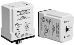
Alternating Relays are used in special applications where the optimization of load usage is required by equalizing the run time of two loads. This alternating action is initiated by a control switch, such as a float switch, manual switch, timing relay, pressure switch, or other isolated contact. Each time the initiating switch is opened, the output relay contacts will change state, thus alternating the two loads. Two LED indicators show load to energize next.
The Alternating Relays listed on this page can be used with one or two control switches & are available in either SPDT or DPDT output configurations (see "Typical Installations" below for more information).
| |  |
| |
| Each version is available with an optional three position selector switch. This allows the unit to alternate the two loads as normal, or lock the relay to one load or the other. By locking the Alternating Relay to one load, the other load can be removed for service without rewiring the first load for continuous operation. The selector switch has a low profile to prevent any accidental changes in status. |
| | |
Features: - For duplex loads
- Can be used with one or two Control Switches
- Control voltages of 12, 24, 120 & 240V AC
- Compact plug-in design utilizing industry-standard 8 or
11 pin octal socket
- 10A SPDT or DPDT Output Configuration
- Optional low profile selector switch to lock in one
sequence
- 2 LEDs indicate load to energize next
| |
| Part Number | Output Contacts | Control Voltage | Wiring Socket |
 ARP012A6 ARP012A6 | SPDT without Selector Switch | 12V AC | 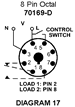 |
|
ARP024A6 | 24V AC |
|
ARP120A6 | 120V AC |
|
ARP240A6 | 240V AC |
|
ARP012A6R | SPDT with Selector Switch | 12V AC |
|
ARP024A6R |
24V AC |
|
ARP120A6R |
120V AC |
|
ARP240A6R |
240V AC |
|
ARP012A2 |
DPDT without Selector Switch |
12V AC |
 |
|
ARP024A2 |
24V AC |
|
ARP120A2 |
120V AC |
|
ARP240A2 |
240V AC |
|
ARP012A2R |
DPDT with Selector Switch |
12V AC |
|
ARP024A2R |
24V AC |
|
ARP120A2R |
120V AC |
|
ARP240A2R |
240V AC |
| Voltage Tolerances: | +10%/-15% of control voltage at 50/60Hz. |
| Load (Burden): | Less than 3VA |
| Output Contacts: | 10A @ 240V AC/30V DC, 1/2HP @ 120/240V AC (N.O.), 1/3HP @ 120/240VAC (N.C.) |
| Life: | Mechanical: 10,000,000 operations, Full Load: 100,000 operations |
| Temperature: | -28° to 65°C (-18° to 149°F) |
| Transient Protection: | 10,000 volts for 20 microseconds |
| Indicator LEDs: | 2 LEDs marked LOAD A and LOAD B |
| Optional Selector Switch Settings: | LOAD 1
ALTERNATE
LOAD 2 |
| Typical Installations |
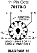
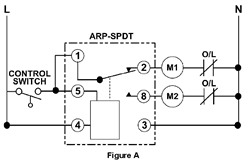
| In the initial off state (Figure A), the Control Switch is open, the Alternating Relay is in the LOAD 1 position, and both loads (M1 & M2) are off. The red LED marked ..LOAD 1.. is ON. When the Control Switch closes, it energizes Load M1. As long as the Control Switch remains closed, Load M1 remains energized. When the Control Switch opens, Load M1 is turned off and the Alternating Relay toggles to the LOAD 2 position. The red LED marked ..LOAD 2.. glows. When the Control Switch closes again, it energizes Load M2. When the Control Switch opens, Load M2 is turned off, the Alternating Relay toggles back to the LOAD 1 position, and the process can be repeated again. On relays with DPDT contacts, two pilot lights can be used for remote indication of LOAD 1 or LOAD 2 status. |
| |
|
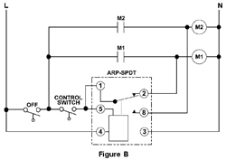
| To eliminate any bounce condition of the Control Switch, the addition of a second switch (OFF) along with two auxiliary contacts is recommended as shown in Figure B. |
|
|
 |
 |
|