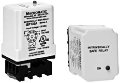
The ISP series of Intrinsically Safe Relays provide a
safe and reliable method to control a load (motor starter, relay, etc.) with an
input device (switch, sensor, etc.) located in a hazardous area. The Instrument
Society of America defines intrinsically safe equipment & wiring in their
specification ISA-RP12.2 as: “equipment and wiring which is incapable of
releasing sufficient electrical or thermal energy under normal or abnormal
conditions to cause ignition of a specific hazardous atmospheric mixture in its
most ignited concentration. Intrinsically safe terminations and wiring may be
brought into any hazardous location of any Group classification for which it is
accepted without requiring explosion-proof housing or other means of
protection”.
UL Listed apparatus provides intrinsically safe
circuits for use in Class I Groups A, B, C, D, Class II Groups E, F, G, and
Class III Hazardous Locations. The ISP relay must be mounted in a non-hazardous
area, following Macromatic Control Drawing Number ISR2A01D. In order to comply
with UL requirements, intrinsically safe and non-intrinsically safe wiring must
be physically separated to prevent inadvertent bypass. |
|  |
| |
Each
ISP relay consists of an intrinsically safe control switch input and an
electromechanical relay output. When the control switch in the hazardous area
is closed, the relay is energized. When the control switch is opened, the relay
is de-energized.
Typical applications include pump lift stations, grain
elevators, refineries and paint rooms. |
| | |
Features: - Provides Low Cost Alternative to Explosion-Proof
Enclosures
- Single Channel
- Isolated 10A SPNO output contact
- 120V AC Input Voltage
- LED Status Indicator
| |
| Input Voltage: | 120V AC, ±10%, 50/60Hz |
| Load (Burden): | 1.25 VA |
| Output Contacts: | SPNO 10A @ 120V AC Resistive |
| Life: | Mechanical: 10,000,000 operations, Full Load: 100,000
operations |
| Response Times: | Operate: 11 ms
Release: 4 ms |
| Temperature: | Operate: -20° to 60°C (-4° to 140°F)
Storage: -45° to 85°C (-49° to 185°F) |
| Insulation Voltage: | 2,000 volts |
| LED Indicator: | Green ON when relay is energized & OFF when relay is
deenergized. |
| Mounting: | Both an integral spring mating clip and the appropriate 8 pin
socket are included with the plug-in relay. |
| UL Control
Drawing ISR2A01D |
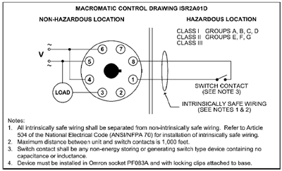 | | | Notes:
1.
All intrinsically safe wiring shall be separated from non-intrinsically safe
wiring. Refer to Article 504 of the National Electrical Code (ANSI/NFPA 70) for
installation of intrinsically safe wiring.
2. Maximum distance between unit
and switch contacts is 1,000 feet.
3. Switch contact shall be any
non-energy storing or generating switch type device containing no capacitance
or inductance.
4. Device must be installed in Omron socket PF083A and with
locking clips attached to base. |
|