| Wago Fieldbus Coupler - CANopen D-Sub 10Kbaud...1Mbaud |
 |
| Part Number |
Conformity Marking |
Approvals |
 750-338 750-338 |
 |
cULus,
cULus-EX, |
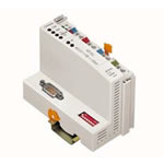
| CANopen FIELDBUS COUPLER D-Sub 10 kBaud - 1 Mbaud; Digital & Analog Signals |
This buscoupler connects the WAGO-I/O-SYSTEM as a slave to the CANopen fieldbus.
The module data is transmitted using PDOs and SDOs.
The buscoupler is capable of supporting all bus modules. The buscoupler automatically configures, creating a local process image which may include analog, digital or specialty modules. Analog and specialty module data is sent via words and/or bytes, digital data is packed into bytes.
CANopen allows the storing of the process image in the corresponding Master control (PLC, PC or NC).
The local process image is divided into two data zones containing the data received and the data to be sent.
The process data can be sent via the CANopen fieldbus to the PLC, PC or NC for further processing, and received from the field via CANopen.
The data of the analog modules is stored in the PDOs according to the order in which the modules are connected to the buscoupler. The bits of the digital modules are sent byte by byte and also mapped in the PDOs. If the amount of digital information exceeds 8 bits, the buscoupler automatically starts with a new byte.
All entries of the object dictionary can be mapped - as the user likes - in the 5 Rx PDOs and 5 Tx PDOs.
The complete input and output process image can be transmitted using SDOs. "Spacer modules" can be set via software.
Note: EDS files required |
|
| Technical Information |
| Characteristic |
Value |
| Max. no. of nodes |
110 |
| Transmission medium |
Shielded Cu-cable 3 x 0.25 mm² |
| Max. length of bus line |
30 M ... 1000 M (DEPENDS ON THE BAUD RATE / CABLE) |
| Baud rate |
10 kBaud ... 1 Mbaud |
| Buscoupler connection |
1 x D-Sub 9; plug |
| Max. no. of I/O modules |
64 |
| Max. fieldbus input image (Byte) |
512 bytes |
| Max. fieldbus output image (Byte) |
512 bytes |
| No. of PDOs |
32 Tx / 32 Rx |
| No. of SDOs |
2 server SDOs |
| Communication profile |
DS-301 V4.1 |
| Device profile |
DS-401 V2.0
Marginal Check
Edge-triggered PDOs
Programmable error response |
| COB ID Distribution |
SDO, Standard |
| Node ID Distribution |
DIP Switches |
| Other CANopen features |
NMT Slave
Minimum Boot-up
Variables PDO Mapping
Emergency Message
Life Guarding
Configuration of Virtual Modules |
| Configuration |
via PC or PLC |
| Voltage supply |
DC 24 V (-15% / + 20%) |
| Input current (max) |
500 mA |
| Efficiency of the power supply |
87% |
| Internal current consumption (5V) |
350 mA |
|
| Characteristic |
Value |
| Total current for the I/O modules (5V) |
1650 mA |
| Isolation |
500 V system / supply |
| Voltage via power jumper contacts (max) |
DC 24 V (-15% / + 20%) |
| Current via power jumper contacts (max) |
DC 10 A |
| Operating temperature |
0 °C ... + 55 °C |
| Storage temperature |
-25 °C ... +85 °C |
| Relative air humidity |
95% |
| Vibration resistance |
acc. IEC 60068-2-6 |
| Shock resistance |
acc. IEC 60068-2-27 |
| Degree of protection |
IP 20 |
| EMC CE-Immunity to interference |
acc. EN 61000-6-2 (2001) |
| EMC CE-Emission of interference |
acc. EN 61000-6-3 (2001) |
| Cross section from [mm²] |
0.08 mm² |
| Cross section to [mm²] |
2.5 mm² |
| Cross section from [AWG] |
28 AWG |
| Cross section to [AWG] |
14 AWG |
| Weight |
200 g |
| Color |
light gray |
| Height |
65 mm |
| Width |
51 mm |
| Depth |
100 mm |
| Strip length from |
8 mm |
| Strip length to |
9 mm |
|
|