| Wago Fieldbus Coupler - DeviceNet 125...500 Kbaud |
 |
| Part Number |
Cert. |
Conformity Marking |
Approvals |
 750-306 750-306
DeviceNet, w status byte |
ODVA |
 |
cULus,
cULus-EX,
KEMA |
750-306/000-005
DeviceNet (only function with digital modules) |
750-306/000-006
DeviceNet (without buscoupler status byte) |
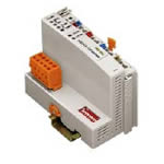
| DeviceNet FIELDBUS COUPLER 125-500 kBaud CARRIER RAIL DIN 35 CAGE CLAMP CONNECTION |
This buscoupler connects the WAGO-I/O-SYSTEM as a slave to the DeviceNet™ fieldbus.
The buscoupler automatically configures, creating a local process image which may include analog, digital or specialty modules. Analog and specialty module data is sent via words and/or bytes, digital data is sent bit by bit.
DeviceNet™ stores the process image in the corresponding Master control (PLC, PC or NC).
The local process image is divided into two data zones containing the data received and the data to be sent. The process data can be sent via the DeviceNetTM fieldbus to the PLC, PC or NC for further processing, and received from the field via DeviceNet™.
The data of the analog modules is stored in the process image which is created automatically according to the order in which the modules are connected to the buscoupler. The bits of the digital modules are sent byte by byte and added to the analog data. If the amount of digital information exceeds 8 bits, the buscoupler automatically starts with a new byte. Note: EDS files required |
|
| Technical Information |
| Characteristic |
Value |
| Max. no. of nodes |
64 with scanner |
| Max. no. Of I/O points |
ca. 6000 (depends on Master) |
| Transmission medium |
shielded Cu- cabletrunk line: 2 x 0.82mm² + 2 x 1.7 mm²drop line: 2 x 0.2mm² + 2 x 0.32 mm² |
| Max. length of bus line |
100 m ... 500 m (depends on the baud rate / on the cable) |
| Baud rate |
125 kBaud, 250 kBaud, 500 kBaud |
| Buscoupler connection |
5-POLE MALE CONNECTOR, SERIES 231 (MCS); CONNECTOR 231-305/010-000/050-000 IS INCLUDED |
| UL 508 |
E175199, UL 508 |
| UL 1604 |
E198726, UL 1604 Class 1 Dev2 ABCD T4A |
| KEMA |
01ATEX1024X Eex nA II T4 |
| Certification |
ODVA |
| Conformity marking |
CE |
| Max. no. of I/O modules |
64 |
| Max. fieldbus input image (Byte) |
512 Byte |
| Max. fieldbus output image (Byte) |
512 Byte |
| Configuration |
via PC or PLC |
| DeviceNet characterictic |
Polled I / O Message ConnectionStrobed I / O Message ConnectionChange of State / Cyclic Message Connection Group 2 only Slave |
| Voltage supply |
DC 24 V (-15% / + 20%) |
| Current consumption using a power supply |
< 500 mA / 24 V |
| Power consumption via CAN interface |
< 120 mA / 11 V |
| Efficiency of the power supply |
87% |
|
| Characteristic |
Value |
| Internal current consumption |
350 mA |
| Total current for the I/O modules |
1650 mA |
| Isolation |
500 V system / supply |
| Voltage via power jumper contacts (max) |
DC 24 V (-15% / + 20%) |
| Current via power jumper contacts (max) |
DC 10 A |
| Operating temperature |
0 °C ... + 55 °C |
| Storage temperature |
-25 °C ... +85 °C |
| Relative air humidity |
95% |
| Vibration resistance |
acc. IEC 60068-2-6 |
| Shock resistance |
acc. IEC 60068-2-27 |
| Degree of protection |
IP 20 |
| EMC immunity to interference |
acc. EN 50082-2 (96) |
| EMC emission of interference |
per EN 50081-1 (93) |
| Cross section from [mm²] |
0.08 mm² |
| Cross section to [mm²] |
2.5 mm² |
| Cross section from [AWG] |
28 AWG |
| Cross section to [AWG] |
14 AWG |
| Voltage CSA |
24 V |
| Weight |
220.39 g |
| Color |
light gray |
| Height |
65 mm |
| Height |
2.56 in |
| Width |
51 mm |
| Width |
2.008 in |
| Depth |
100 mm |
| Depth |
3.937 in |
| Strip length from |
8 mm |
| Strip length to |
9 mm |
| Strip length |
0.33 in |
|
|