| Wago Fieldbus Coupler - PROFIBUS DP 1.5 Mbaud |
 |
| Part Number |
Standard |
Conformity Marking |
Approvals |
 750-331 750-331 |
EN 50170 |
 |
cULus, |
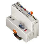
| PROFIBUS DP FIELDBUS COUPLER 1,5 MBaud LWL-CONNECTION CARRIER RAIL DIN 35 CAGE CLAMP CONNECTION |
This buscoupler allows connection of the WAGO-I/O-SYSTEM as a slave to the PROFIBUS DP fieldbus.
The buscoupler is capable of supporting all bus modules. The buscoupler automatically configures, creating a local process image which may include analog, digital or specialty modules. Analog and specialty module data is sent via words and/or bytes, digital data is sent bit by bit.
The local process image is divided into two data zones containing the data received and the data to be sent. The process data can be sent via the PROFIBUS DP fieldbus to the PLC, PC or NC for further processing, and received from the field via PROFIBUS DP.
The data of the analog modules is stored in the process image which is created automatically according to the order in which the modules are connected to the buscoupler. The bits of the digital modules are sent byte by byte and added to the analog data. If the amount of digital information exceeds 8 bits, the buscoupler automatically starts with a new byte.
For the operation of a PROFIBUS DP coupler with fiber optic cable connection, an interface module is also necessary to transfer RS 485 on an fiber optic ring. A subring can contain up to 10 other fiber optic modules. The baud rate is set via two DIP switches on the buscoupler. Note: GSD files required |
|
| Technical Information |
| Characteristic |
Value |
| No. of I/O- Modules in subring |
10 |
| Transmission medium |
APF 1000?m |
| Max. length of fieldbus segment |
1 m ... 25 m |
| Topology |
subring, single faser ring |
| Baud rate |
93.75 kBaud ... 1500 kbaud |
| Buscoupler connection |
HP Simplex LWL-plug is included |
| UL 508 |
E175199, UL 508 (applied for) |
| Standard |
EN 50170 |
| Conformity marking |
CE |
| Max. no. of I/O modules |
64 |
| Max. fieldbus input image (Byte) |
128 Byte |
| Max. fieldbus output image (Byte) |
128 Byte |
| Configuration |
via PC or PLC |
| Voltage supply |
DC 24 V (-15% / + 20%) |
| Input current (max) |
500 mA |
| Efficiency of the power supply |
87% |
| Internal current consumption |
350 mA |
| Total current for the I/O modules |
1650 mA |
| Isolation |
500 V system / supply |
| Voltage via power jumper contacts (max) |
DC 24 V (-15% / + 20%) |
|
| Characteristic |
Value |
| Current via power jumper contacts (max) |
DC 10 A |
| Operating temperature |
0 °C ... + 55 °C |
| Storage temperature |
-25 °C ... +85 °C |
| Relative air humidity |
95% |
| Vibration resistance |
acc. IEC 60068- |
| Shock resistance |
acc. IEC 60068- |
| Degree of protection |
IP 20 |
| EMC immunity to interference |
acc. EN 50082- |
| EMC emission of interference |
acc. EN 50081- |
| Cross section from [mm²] |
0.08 mm² |
| Cross section to [mm²] |
2.5 mm² |
| Cross section from [AWG] |
28 AWG |
| Cross section to [AWG] |
14 AWG |
| Voltage CSA |
24 V |
| Color |
light gray |
| Height |
65 mm |
| Height |
2.56 in |
| Width |
51 mm |
| Width |
2.008 in |
| Depth |
100 mm |
| Depth |
3.937 in |
| Strip length from |
8 mm |
| Strip length to |
9 mm |
| Strip length |
0.33 in |
| Weight |
187 g |
|
|