| Wago Fieldbus Coupler - CAL 10 Kbaud...1 Mbaud |
 |
| Part Number |
Conformity Marking |
Approvals |
 750-305 750-305 |
 |
cULus,
cULus-EX,
KEMA |
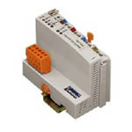
| CAL FIELDBUS COUPLER 10 kBaud - 1 MBaud CARRIER RAIL DIN 35 CAGE CLAMP CONNECTION |
This buscoupler allows connection of the WAGO-I/O-SYSTEM as a slave to the CAL fieldbus. The module data is transmitted using Communication Objects (COB).
The buscoupler automatically configures, creating a local process image which may include analog, digital or specialty modules. Analog and specialty module data is sent via words and/or bytes, digital data is sent bit by bit.
The local process image is divided into two data zones containing the data received and the data to be sent. The process data can be sent via the CAL fieldbus to the PLC, PC or NC for further processing, and received from the field via CAL.
The data of the analog modules is stored in the process image which is created automatically according to the order in which the modules are connected to the buscoupler. The bits of the digital modules are sent byte by byte and added to the analog data. If the amount of digital information exceeds 8 bits, the buscoupler automatically starts with a new byte. The input and output process image is transmitted using the Basic Domain Protocol.
A Communication Object (COB) is assigned to each channel of an analog module and each digital byte group. They are transmitted using the Basic Variable Protocol. |
|
| Technical Information |
| Characteristic |
Value |
| No. of COB IDs |
25 |
| Transmission medium |
Shielded Cu-cable 3 x 0.25 mm² |
| Max. length of bus line |
1000 m (depends on the baud rate / on the cable) |
| Baud rate |
10 kBaud ... 1 MBaud |
| Buscoupler connection |
5 pole male connector, series 231 (MCS) female connector 231-305/ 010-000 is included |
| UL 508 |
E175199, UL 508 |
| UL 1604 |
E198726, UL 1604 Class 1 Dev2 ABCD T4A |
| KEMA |
01ATEX1024X Eex nA II T4 |
| Conformity marking |
CE |
| Max. no. of I/O modules |
64 |
| Max. fieldbus input image (Byte) |
512 Byte |
| Max. fieldbus output image (Byte) |
512 Byte |
| Configuration |
via PC or PLC |
| Voltage supply |
DC 24 V (-15% / + 20%) |
| Input current (max) |
500 mA |
| Efficiency of the power supply |
87% |
| Internal current consumption |
350 mA |
| Isolation |
500 V system / supply |
| Voltage via power jumper contacts (max) |
DC 24 V (-15% / + 20%) |
| Current via power jumper contacts (max) |
DC 10 A |
|
| Characteristic |
Value |
| Operating temperature |
0 °C ... + 55 °C |
| Storage temperature |
-25 °C ... +85 °C |
| Relative air humidity |
95% |
| Vibration resistance |
acc. IEC 60068-2-6 |
| Shock resistance |
acc. IEC 60068-2-27 |
| Degree of protection |
IP 20 |
| EMC immunity to interference |
acc. EN 50082-2 (96) |
| EMC emission of interference |
acc. EN 50081-2 (94) |
| Cross section from [mm²] |
0.08 mm² |
| Cross section to [mm²] |
2.5 mm² |
| Cross section from [AWG] |
28 AWG |
| Cross section to [AWG] |
14 AWG |
| Voltage CSA |
24 V |
| Weight |
205 g |
| Color |
light gray |
| Height |
65 mm |
| Height |
2.56 in |
| Width |
51 mm |
| Width |
2.008 in |
| Depth |
100 mm |
| Depth |
3.937 in |
| Strip length from |
8 mm |
| Strip length to |
9 mm |
| Strip length |
0.33 in |
|
|