 |
| Wago IO System - System Modules |
| Wago Main Page |
| I/O Products |
|
| Fieldbus Coupler |
| Programmable Feildbus Controller |
| Digital Input Modules |
| Digital Output Modules |
| Analog Input Modules |
| Analog Output Modules |
| Specialty Modules |
| System Modules |
 |
| Binary
Spacer Module w/ Power Supply |
| Bus Ext.
End Module |
| Bus Ext.
Coupler Module |
| End
Module |
| Field
Side Connection Module, 0-230V AC / DC |
| Field
Side Connection Module, 24V DC |
| Field
Side Connection Module, 0V DC |
| Filter
Module, System & Field Sides |
| Internal
System Supply Module, 24V DC |
| Overvoltage Protection, Field Side |
| Separation Module |
| Separation Module w/ Contacts |
| Separation Module, 24V DC, 230V AC |
| Supply
Module, 24V DC |
| Supply
Module, 0-230V AC/DC |
| Supply
Module w/ fuse, 24V DC |
| Supply
Module w/ fuse, 230V AC |
| Supply
Module w/ fuse, 120V AC |
| Supply
Module w/ fuse & diagnostics, 24V DC |
| Supply
Module w/ fuse & diagnostics, 120V AC |
| Supply
Module, EEx i, 24V DC |
|
|
| Approvals |
|
| Wago System Modules |
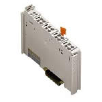 |
System Module Housing
The electronics of the WAGO I/O modules are located in 3 different housings.
The width of the module with special functions is 12 mm or 24 mm. The electronics of the buscouplers are integrated in a housing with a width of approximately 51 mm.
The modules with special functions may contain up to 3 power jumper contacts which realize a through connection. Depending on the application, all modules are equipped with up to 4 LEDs (12 mm housing) or up to 8 LEDs (24 mm housing).
|
ATTENTION:
Depending on the I/O function, some modules do not have power jumper contacts (e.g. 4-channel modules). A module which needs all contacts may be connected to the right-hand side of modules which do not have 3 power jumper contacts. Please review the circuit diagrams of the individual modules (found on the .pdf file). An additional power supply module may be necessary.
Note: A bus end module is always required at the end of each node (
 750-600 ), opposite end from the buscoupler, to complete the node. 750-600 ), opposite end from the buscoupler, to complete the node. |
|
| Modules |
| Binary Spacer w/ Power Supply |
Separation Module w/ Contacts |
| Bus Ext. End Module |
Separation Module, 24V DC, 230V AC |
| Bus Ext. Coupler Module |
Supply Module, 24V DC |
| End Module |
Supply Module, 0-230V AC/DC |
| Field Side Connection, 0-230V AC / DC |
Supplyw/ fuse, 24V DC |
| Field Side Connection, 24V DC |
Supply w/ fuse, 230V AC |
| Field Side Connection, 0V DC |
Supply w/ fuse, 120V AC |
| Filter Module, System & Field Sides |
Supply w/ fuse & diagnostics, 24V DC |
| Internal System Supply Module, 24V DC |
Supply w/ fuse & diagnostics, 120V AC |
| Overvoltage Protection, Field Side |
Supply Module, EEx i, 24V DC |
| Separation Module |
|
|
|