| | | The following Tools are Suitable for Small Volume Assembly or Hobbyist Applications | | | 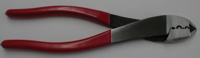
Crimp Tool | | Part Number | Description | Web Special Price |  PP-CRIMPER PP-CRIMPER | Hand Crimp Tool for 15, 30, 45, AND 75 amp contacts. | | | This versatile Hand Crimper is capable of crimping the 15, 30, 45, and 75 amp contacts for Anderson PowerPoles. | This tool handles most small volume and hobbyist applications without the expense of a genuine Anderson Crimper. Many Anderson Users report excellent results using this reliable tool.
If you are planning to crimp hundreds of contacts, we recommend considering the purchase of an Anderson CrImper as this will ensure quality, consistant crimps every time.
| | | | | | Please refer to this guide, based on guides by Radio Club Users, to ensure excellent results using this crimper. | | | | Assemble the red and black plastic housings together correctly on the first try, they fit snugly and can be difficult to get apart. The picture below shows the standard orientation for ARES /RACES applications. Note that you can assemble them in other ways for other applications. | 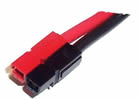 | Put the connector housings together, before, putting the connector pins in, this is easier when using heavy paired wire.
Before soldering or crimping the contacts on to heavy paired wire, orient them so that they go in the housings without twisting the wire.
The plastic housings are held together with dovetail joints. Always slide these joints together! They will be damaged if you try to snap them together or apart. They ONLY slide together in one direction, this should be obvious by looking at them carefully.
The contacts go in the housings in only one way. Insert the contacts with their sharp edge down against the flat spring that is in the housing. They should slide in and click. If you do not hear a click or they are not fully seated, fix it. When they are inserted fully you should notice that the contact and it's wire "floats" slightly in the housing, if it feels tight it may not be snapped in fully. Tug slightly to make sure the contact is locked in place. If you have trouble getting the contact in to the housing you may have squashed the contact wider or it is bent.
When soldering the contact pins, be careful not to use too much solder. Keep the solder inside, where the wire goes. If a blob of solder gets on the outside of the connector body you may have trouble putting the contact in the housing. If you get solder on the contact surface you will not make a good contact.
When crimping the contact pins use a crimp that contains the wire completely inside the pin and doesn't spread the connector apart. A good crimp is one where the dimensions of the crimped portion are no more than an uncrimped pin. If the crimp is flattened out you will not be able to easily push the pin in to the body. If you bend the contact blade in relation to the crimp area you should straighten it before putting it in to the body.
It is possibly to use larger or smaller gauge wire with the 30 and 45 amp connectors. The 30 amp connector pins will work with #10 wire if you cut the end cleanly and carefully put each and every strand of that wire in to the pin. It may be is easier to use 45 amp connectors on #10 wire. Using 16 gauge or smaller wire in a 30 amp contact requires that you double or triple up the wire to fill the crimp area of the contact to get a good crimp.
A properly crimped contact should have a minimum hold on the wire of more than 25 pounds. A pair of connectors should snap together with 8 to 10 pounds force.
Last but not least, MAKE SURE you have the polarity correct before plugging in your equipment. | | | | POWERPOLE INSTALLATION USING THE PP-CRIMPER Tool | Read above, the general instructions apply when using the PP-CRIMPER tool that we supply.
This tool is a very nice, inexpensive crimping tool but it was not designed specifically for Anderson PowerPoles. It is not a full substitute for a real Anderson crimping tool. The real Anderson tool is (click here). You may want to buy the real thing if you are going to do hundreds of PowerPoles. Purchasing one Anderson tool for a club or group might be a good idea in an effort to standardize DC connections for emergency setups.
The PP-CRIMPER was suggested to us by hams that were already using it with PowerPoles. You can't beat it for the price. It makes putting the connectors on easily, certainly easier than soldering.
Looking at the PP-CRIMPER tool you will see it has three crimping dies and a cutter. We will refer to the dies as number one being closest to the cutter and number three being closest to the hinge.
You may use the cutters to cut the wire but you will need wire strippers to strip the wire. Using cutters to strip wire will probably nick the wire strands. Strip the wire insulation back 5/16" for 15-45 amp contacts and 9/16" for 75 amp contacts, try not to nick the strands. | | | | THE FOLLOWING IS FOR 15, 30, and 75 AMP CONNECTORS | Put the contact over the wire making sure that all of the strands are inside the contact and the insulation is not. You will find it is possible to use up to 10 gauge wire in a 30 amp contact even though they are made for 12 to 14 gauge. The # 10 will have to be cut cleanly and you have to neatly twist it to get all of the strands inside. Smaller than # 14 will have to be doubled or tripled over to fill the contact recess and get a good crimp.
If you are using paired wire orient the wire with the red/plus wire on your right with the end of the wire away from you. Place the contact on the wire so that the sharp edge of the contact tip is down. Do both contacts this way and when crimped they will fit in to the plastic housing correctly without twisting the wire.
Put the contact in to the smaller number one die. Center the crimp portion of the contact in the die with the rounded portion of the die up and against the seam on the contact and the tongue of the die directly opposite. Make sure that the wire is fully inserted in to the contact and crimp down firmly. Crimp with almost but not quite full force without bottoming out the tool. You will notice that the crimp is now slightly wider than it was. Rotate the crimp 90 degrees and squeeze it again in the number three die but this time not as firmly. The idea is to make the width of the crimp just slightly less that it was uncrimped. Repeat the first crimp in the first die, but with less pressure.
AGAIN, MAKE SURE you have the polarity correct before plugging in you equipment. | | | | THE FOLLOWING IS FOR 45 AMP CONNECTORS | | The PP-CRIMPER tool may also be used for 45 amp contact but and extra step is required. These contacts come with the crimp portion open in a spread out "U". It is helpful to close up the "U" slightly with the front edge of the number one die. Put the crimp in the die like the 30 amp but put the wire in after the crimp contact is held inside the tool. The 45 amp contacts will easily take # 10 wire and will almost take #8, you will probably have a problem getting the number # 8 wires insulation inside the plastic housings. To use the 45's with the larger wire, # 10 or higher, you should use the larger # 2 die instead of the smaller # 1. | | | 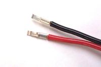
PowerPole 30 amp contacts. The top one is installed with the $18.00 PP-CRIMPER tool
and the bottom one was installed with a $700.00 Anderson pneumatic tool. | | | 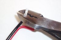
This is the first crimp of a PowerPole 30 amp contact. Notice it is in the first die #1 with #12 wire and that the seam in the contact is against the rounded side of the tool's die. Make sure the end of the contact's crimp section is just below flush on the side of the tool. | | |
| 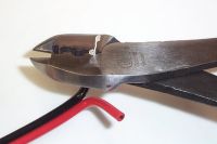
This is the 2nd step of a PowerPole 30 amp contact. Notice that the contact is in the back die # 3 and is turned 90degrees. Do not crimp this very much, just enough to make the width of the crimped section less that what it was before you started. Again make sure the end of the contact's crimp section is just below flush on the side of the tool. |
| 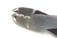
This is the 1st step of a PowerPole 45 amp contact. It is just squeezed slightly together before putting the wire in so that in the next step the sides of the crimp will form inward. If you skip this step you may have to toss the contact and start over. |
| 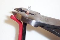
This the crimp of the 45 amp contact. It is in the larger die #3 with # 10 wire. Again notice that the contact is below flush on the side of the tool. You still must do the sideways light crimp to reduce the width of the finished crimp so that it will fit in the housing. You may want to repeat step 2 and 3. | |