| Wago Main Page |
| I/O Products |
|
| Fieldbus Coupler |
| Programmable Feildbus Controller |
| Digital Input Modules |
 |
| 1 Channel |
| NAMUR,
EEx i |
| 2 Channel |
| 24V DC, 3.0 ms |
| 24V DC, 0.2 ms |
| 24V DC, 3.0 ms, proximity
switch |
| 24V DC, 0.2 ms, proximity
switch |
| 24V DC, 3.0 ms, diagnostics,
acknowledgment |
| 24V DC, 3.0 ms, diagnostics |
| 24V DC, intruder detection |
| 48V DC, 3.0 ms |
| 110V DC, high-side/low-side
switching |
| 120V DC |
| 230V DC |
| NAMUR |
| 4 Channel |
| 5V DC, 0.2 ms |
| 24V DC, 3.0 ms |
| 24V DC, 0.2 ms |
| 24V DC, 3.0 ms, 2-conductor |
| 24V DC, 0.2 ms, 2-conductor |
| 24V DC, pulse extension |
| 24V DC, 3.0 ms, low-side switching |
| 24V DC, 0.2 ms, low-side switching |
| 24V AC/DC, 20 ms |
| 24V AC/DC, pow. contacts 50 ms |
| 42V AC/DC |
| 8 Channel |
| 24V DC, 3.0 ms |
| 24V DC, 0.2 ms |
|
|
| Digital Output Modules |
| Analog Input Modules |
| Analog Output Modules |
| Specialty Modules |
| System Modules |
| Approvals |
|
| Wago Digital Input Modules |
 |
| Part Number |
Conformity Marking |
Approvals |
 750-418 750-418 |
 |
cULus,
cULus-EX
KEMA |
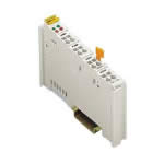
| 2-CHANNEL DIGITAL INPUT MODULE DC 24 V POSITIVE SWITCHING CARRIER RAIL DIN 35 CAGE CLAMP CONNECTION |
| The digital input module receives control signals from the field side and supplies a short-circuit proof voltage to the sensors. The module transfers the control signals and other information via fieldbus coupler to a supervisory control. Each input module has a noise-rejection filter. Each sensor can be supplied separately. A short circuit to ground is indicated as an error/fieldbus failure and a message is sent to the supervisory control. After the error has been eliminated the input module
750-418 will require an acknowledgement (performed by the operator via control). The input module
750-419 will acknowledge automatically. An optocoupler is used for electrical isolation between the bus and the field side. |
|
| Technical Information |
| Characteristic |
Value |
| No. of inputs |
2 |
| Number of outputs |
2 FOR TRANSMITTER SUPPLY |
| CURRENT CONSUMPTION (INTERNAL) (<) mA |
0 mA |
| Voltage via power jumper contacts (max) |
DC 24 V (-15% / + 20%) |
| Signal voltage (0) |
DC -3 V ... +5 V |
| Signal voltage (1) |
DC 15 V ... 30 V |
| Input filter (ms) |
3 ms |
| Current supply (typ) |
3.7 mA |
| Sensor supply Uv1,2 |
DC 24 V |
| Output current max. (A) |
0.5 A |
| Short-circuit current |
1.5 A, undulating because of thermal overload protection |
| Internal data width |
4 BITS IN; 4 BITS OUT |
| Isolation |
500 V system / supply |
| Operating temperature |
0 °C ... + 55 °C |
| Storage temperature |
-25 °C ... +85 °C |
| Relative air humidity |
95% |
| Vibration resistance |
acc. IEC 60068-2-6 |
| Shock resistance |
acc. IEC 60068-2-27 |
| Degree of protection |
IP 20 |
|
| Characteristic |
Value |
| EMC immunity to interference |
acc. EN 50082-2 (96) |
| EMC emission of interference |
per EN 50081-1 (93) |
| UL 508 |
E175199, UL 508 (applied for) |
| Conformity marking |
CE |
| Cross section from [mm²] |
0.08 mm² |
| Cross section to [mm²] |
2.5 mm² |
| Cross section from [AWG] |
28 AWG |
| Cross section to [AWG] |
14 AWG |
| Weight |
51 g |
| Color |
light gray |
| Height |
64 mm |
| Height |
2.52 in |
| Width |
12 mm |
| Width |
0.472 in |
| Depth |
100 mm |
| Depth |
3.937 in |
| Strip length from |
8 mm |
| Strip length to |
9 mm |
| Strip length |
0.33 in |
|
|
|