| Wago Programmable Fieldbus Controller |
 |
| Part Number |
Conformity Marking |
Approvals |
 750-837 750-837 |
 |
cULus,
ABS*, BV*, DNV*,
GL*, LR*, RINA*,
cULus-EX,
KEMA |
|
750-626 filter module is absolutely necessary |
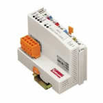
| CANopen PROGRAMMABLE FIELDBUS CONTROLLER 10 kBaud - 1 MBaud CARRIER RAIL DIN 35 CAGE CLAMP CONNECTION |
The programmable fieldbus controller for CANopen combines the functionality of the CANopen fieldbus coupler with the functionality of a Programmable Logic Control (PLC). Programming of the application is done with WAGO-I/O-PRO 32 in accordance with IEC 61131-3, covering all 5 programming languages. The programmer can access all fieldbus and I/O data. Characteristics and use:
l The use of decentralized control can better support a PLC or PC
l Signal pre-processing reduces fieldbus transmissions
l Complex applications can be divided into multiple tasks
l Tasks can be prioritized
l Peripheral equipment can be controlled directly, resulting in faster system response times
l Programmable response in the event of a fieldbus failure
l Simple, self-sufficient control
Note: EDS files required |
|
| Technical Information |
| Characteristic |
Value |
| Max. no. of nodes |
110 |
| Transmission medium |
Shielded Cu-cable 3 x 0.25 mm² |
| Max. length of bus line |
30 M ... 1000 M (DEPENDS ON THE BAUD RATE / ON THE CABLE) |
| Baud rate |
10 kBaud ... 1 MBaud |
| Buscoupler connection |
5 pole male connector, series 231 (MCS) female connector 231-305/ 010-000 is included |
| Programming |
WAGO-I/O-PRO 32 |
| UL 508 |
E175199, UL 508 (applied for) |
| IEC 61131-3 |
AWL, KOP, PUP, ST, AS |
| Conformity marking |
CE |
| Max. no. of I/O modules |
64 |
| Max. fieldbus input image (Byte) |
512 Byte |
| Max. fieldbus output image (Byte) |
512 Byte |
| Input variables |
512 Byte |
| Output variables |
512 Byte |
| Configuration |
automatic |
| Program memory |
128 kByte |
| Data memory |
64 kByte |
| Non-volatile memory (retain) |
8 kByte |
| Cycle time |
< 3 ms for 1000 statements / 256 dig. I/Os |
| No. of PDOs |
32 Tx / 32 Rx |
| No. of SDOs |
3 SERVER SDO / 16 CLIENT SDO |
| Communication profile |
DS-301 V4.01 |
| Device profile |
DS-401 V 2.0DS-401 V2.0 marginal check edge-triggeredPDOs programmable error response DSP 405 NMTmaster can be programmed using function blocks |
| COB ID Distribution |
SDO, Standard |
| Node ID Distribution |
DIP Switch |
| Other CANopen features |
NMT Slave ; Minimum Boot-up ; Variables PDO Mapping ;Emergency Message ; Life Guarding / Heartbeat ;Leermodulkonfiguration |
|
| Characteristic |
Value |
| Configuration |
via PC or PLC |
| Voltage supply |
DC 24 V (-25% / + 30%) |
| Input current (max) |
500 mA |
| Efficiency of the power supply |
87% |
| Internal current consumption |
350 mA |
| Total current for the I/O modules |
1650 mA |
| Isolation |
500 V system / supply |
| Voltage via power jumper contacts (max) |
DC 24 V (-25% / + 30%) |
| Current via power jumper contacts (max) |
DC 10 A |
| Operating temperature |
0 °C ... + 55 °C |
| Storage temperature |
-25 °C ... +85 °C |
| Relative air humidity |
95% |
| Vibration resistance |
acc. IEC 60068-2-6 |
| Shock resistance |
acc. IEC 60068-2-27 |
| Degree of protection |
IP 20 |
| EMC immunity to interference |
acc. EN 50082-2 (96) |
| EMC emission of interference |
acc. EN 50081-2 (94) |
| EMC marine applications - noise proof |
gem. Germanischer Lloyd (1997) |
| EMC marine applications - noise transmission |
gem. Germanischer Lloyd (1997) |
| Cross section from [mm²] |
0.08 mm² |
| Cross section to [mm²] |
2.5 mm² |
| Cross section from [AWG] |
28 AWG |
| Cross section to [AWG] |
14 AWG |
| Weight |
200 g |
| Color |
light gray |
| Height |
65 mm |
| Height |
2.56 in |
| Width |
51 mm |
| Width |
2.008 in |
| Depth |
100 mm |
| Depth |
3.937 in |
| Strip length from |
8 mm |
|
|