| Wago Programmable Fieldbus Controller |
 |
| Part Number |
Conformity Marking |
Approvals |
 750-806 750-806 |
 |
cULus,
cULus-EX,
KEMA |
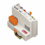
| DEVICENET PROGRAMMABLE FIELDBUS -CONTROLLER 125-500 kBaud CARRIER RAIL DIN 35 CAGE CLAMP CONNECTION |
The programmable fieldbus controller for DeviceNetTM combines the functionality of the DeviceNetTM fieldbus coupler with the functionality of a Programmable Logic Control (PLC). Programming of the application is done with WAGO-I/O-PRO 32 in accordance with IEC 61131-3, covering all 5 programming languages. The programmer can access all fieldbus and I/O data. Characteristics and use:
l The use of decentralized control can better support a PLC or PC
l Signal pre-processing reduces fieldbus transmissions
l Complex applications can be divided into multiple tasks
l Tasks can be prioritized
l Peripheral equipment can be controlled directly, resulting in faster system response times
l Programmable response in the event of a fieldbus failure
l Simple, self-sufficient control
Note: EDS files required |
|
| Technical Information |
| Characteristic |
Value |
| Max. no. of nodes |
64 with scanner |
| Max. no. Of I/O points |
ca. 6000 (depends on Master) |
| Transmission medium |
shielded Cu- cabletrunk line: 2 x 0.82mm² + 2 x 1.7 mm²drop line: 2 x 0.2mm² + 2 x 0.32 mm² |
| Total length |
100 m ... 500 m (depends on the baud rate / on the cable) |
| Baud rate |
125 kBaud, 250 kBaud, 500 kBaud |
| Buscoupler connection |
5-POLE MALE CONNECTOR, SERIES 231 (MCS); CONNECTOR 231-305/010-000/050-000 IS INCLUDED |
| Programming |
WAGO-I/O-PRO 32 |
| IEC 61131-3 |
AWL, KOP, PUP, ST, AS |
| UL 508 |
E175199, UL 508 |
| UL 1604 |
E198726, UL 1604 Class 1 Dev2 ABCD T4A |
| Conformity marking |
CE |
| Max. no. of I/O modules |
64 |
| Max. fieldbus input image (Byte) |
1024 Byte |
| Max. fieldbus output image (Byte) |
1024 Byte |
| Input variables |
512 Byte |
| Output variables |
512 Byte |
| Program memory |
128 kByte |
| Data memory |
64 kByte |
| Non-volatile memory (retain) |
8 kByte |
| Cycle time |
< 3 ms for 1000 statements / 256 dig. I/Os |
| Configuration |
via PC or PLC |
| DeviceNet characterictic |
POLLED I/O MESSAGE CONNECTION; STROBED I/OMESSAGE CONNECTION; CHANGE OF STATE /CYCLIC MESSAGE CONNECTION; UCMM; DEVICENETMASTER CAN BE PROGRAMMED USING FUNCTIONBLOCKS |
|
| Characteristic |
Value |
| Voltage supply |
DC 24 V (-15% / + 20%) |
| Current consumption using a power supply |
< 500 mA / 24 V |
| Power consumption via CAN interface |
< 120 mA / 11 V |
| Efficiency of the power supply |
87% |
| Internal current consumption |
350 mA |
| Total current for the I/O modules |
1650 mA |
| Isolation |
500 V system / supply |
| Voltage via power jumper contacts (max) |
DC 24 V (-15% / + 20%) |
| Current via power jumper contacts (max) |
DC 10 A |
| Operating temperature |
0 °C ... + 55 °C |
| Storage temperature |
-25 °C ... +85 °C |
| Relative air humidity |
95% |
| Vibration resistance |
acc. IEC 60068-2-6 |
| Shock resistance |
acc. IEC 60068-2-27 |
| Degree of protection |
IP 20 |
| EMC immunity to interference |
acc. EN 50082-2 (96) |
| EMC emission of interference |
per EN 50081-1 (93) |
| Cross section from [mm²] |
0.08 mm² |
| Cross section to [mm²] |
2.5 mm² |
| Cross section from [AWG] |
28 AWG |
| Cross section to [AWG] |
14 AWG |
| Weight |
200 g |
| Color |
light gray |
| Height |
65 mm |
| Height |
2.56 in |
| Width |
51 mm |
| Width |
2.008 in |
| Depth |
100 mm |
| Depth |
3.937 in |
| Strip length from |
8 mm |
| Strip length to |
9 mm |
| Strip length |
0.33 in |
|
|